Carbon Capture and Storage: Innovations Reducing Emissions Across Oil and Gas Operations
Upstream and midstream operators face a compounding problem: regulatory pressure on Scope 1 and Scope 2 emissions is accelerating while asset retirement obligations and production targets remain unchanged. Facilities that cannot demonstrate credible emissions reduction pathways are already encountering financing constraints, permit delays, and in some jurisdictions, mandatory curtailment. Carbon Capture and Storage (CCS) has moved from a long-range decarbonisation concept into an operational tool that engineering teams are being asked to specify, procure, and integrate into existing infrastructure — often without a clear picture of which technology tier fits their site conditions, risk profile, or budget cycle.
This article surveys the current CCS technology landscape, flags the geomechanical and geochemical factors that dominate geological storage risk, and gives procurement and maintenance teams a structured basis for evaluation.
The Technology Stack: Capture First
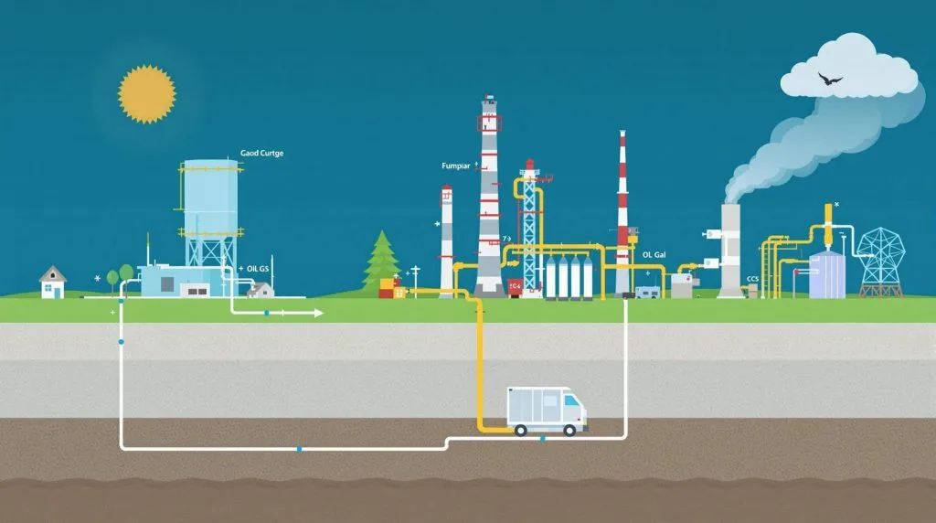
CCS is a chain of unit operations: capture, compression and conditioning, transport, and geological injection. Failures compound across the chain, so each link must be evaluated independently.
Post-Combustion Capture
Post-combustion capture intercepts CO₂ from flue gas after fuel combustion. Amine scrubbing — typically monoethanolamine (MEA) or blended amines — remains the most field-proven approach. The solvent absorbs CO₂ at low temperature and releases it under heat, producing a concentrated stream suitable for compression. The energy penalty associated with solvent regeneration is the dominant operating cost driver; reducing that penalty is the focus of most current solvent R&D.
Solid sorbents, including zeolites and metal-organic frameworks (MOFs), are being evaluated as lower-energy alternatives. MOFs offer high surface area and tunable pore chemistry, but long-term sorbent stability under real flue gas conditions — which contain SOₓ, NOₓ, and particulates — remains an open engineering question rather than a solved one. The RSC Advances review on advanced materials and AI for CCUS notes that integrating machine learning with sorbent screening is shortening the materials discovery cycle, allowing researchers to identify candidates with improved selectivity and regeneration characteristics faster than conventional experimental programmes.
Pre-Combustion and Oxyfuel Capture
Pre-combustion capture applies to gasification and reforming processes: fuel is converted to a hydrogen-rich syngas, CO₂ is separated before combustion, and hydrogen is burned. This approach is relevant to refineries with existing hydrogen production units and to facilities exploring blue hydrogen pathways.
Oxyfuel combustion replaces air with near-pure oxygen, producing a flue gas that is predominantly CO₂ and water vapour, simplifying separation. The air separation unit (ASU) represents a significant capital and energy cost; cryogenic ASUs are mature but energy-intensive, and advances in ion transport membranes are being pursued to reduce that load.
Electrochemical Capture
A notable development published in Nature Chemical Engineering (2026) describes a membraneless electrochemical architecture for CO₂ capture. The approach uses electrochemically driven pH swings to absorb and release CO₂ without the membrane fouling that has limited earlier electrochemical designs. The absence of a membrane simplifies the cell architecture and reduces a significant maintenance burden. While this technology is at an earlier readiness level than amine scrubbing, it represents a credible path toward modular, lower-footprint capture units suitable for offshore or space-constrained onshore installations.
Biotechnological Routes
Biological capture mechanisms — including engineered microalgae, carbonic anhydrase enzyme systems, and microbial electrosynthesis — are reviewed in the Frontiers in Climate publication (2026). These approaches can operate at ambient conditions and, in some configurations, convert captured CO₂ into usable products rather than requiring permanent geological disposal. For oil and gas operators, the near-term relevance is limited to specific applications such as produced water treatment or enhanced oil recovery where biological activity is already managed, but the longer-term potential for integration into facility carbon management plans warrants tracking.
Geological Storage: Where Most Projects Fail or Succeed
Capture technology selection matters, but geological storage is where CCS projects most frequently stall. The Sustainability journal's comprehensive review of geomechanical and geochemical aspects (2025) provides a systematic treatment of the risk factors that engineering teams must address before committing to an injection site.
Geomechanical Considerations
Injecting supercritical CO₂ into a saline aquifer or depleted reservoir increases pore pressure. If that pressure increase exceeds the fracture gradient of the caprock, seal integrity is compromised. Key parameters to characterise before injection design include:
- In-situ stress state: horizontal and vertical stress magnitudes and orientations determine which fault orientations are critically stressed
- Caprock mechanical properties: tensile strength, Young's modulus, and creep behaviour under sustained pressure
- Fault proximity and orientation: pre-existing faults can act as preferential migration pathways if reactivated
Induced seismicity is a geomechanical risk that must be mitigated through injection design (pressure management, injection rate control, well placement relative to faults) and addressed in the monitoring and measurement plan to detect and respond to any events that occur. The review notes that geomechanical modelling should be coupled with reservoir simulation rather than run as a standalone assessment.
Geochemical Considerations
Dissolved CO₂ forms carbonic acid, which reacts with formation minerals and well cement. Dissolved CO₂ forms carbonic acid, which reacts with formation minerals and well cement. In carbonate-rich formations, CO₂-induced dissolution can improve injectivity over time, but may also weaken carbonate caprocks if they are exposed to the acidic plume. In siliciclastic formations, mineral precipitation can reduce permeability around the wellbore, but the extent depends on formation mineralogy, pH, and temperature conditions and must be assessed through site-specific geochemical modelling. Well cement integrity — particularly in legacy wells within the area of review — must be assessed against the expected CO₂ plume migration path and geochemical conditions. Well cement integrity — particularly in legacy wells within the area of review — must be assessed against the expected CO₂ plume migration path. This is directly relevant to operators with mature fields where legacy well data may be incomplete.
Monitoring Requirements
Regulatory frameworks in most jurisdictions require a Measurement, Monitoring and Verification (MMV) plan. This typically includes:
- Baseline seismic surveys prior to injection
- Downhole pressure and temperature gauges on injection wells
- Periodic 4D seismic or microseismic monitoring to track plume migration
- Groundwater monitoring wells at the boundary of the area of review
- Atmospheric CO₂ monitoring at surface
The MDPI Materials review (2026) notes that fibre optic distributed temperature sensing (DTS) and distributed acoustic sensing (DAS) along injection wellbores are increasingly being deployed to provide continuous subsurface data at lower cost than conventional wireline campaigns.
AI and Digital Integration
The RSC Advances review highlights a structural shift in how CCS systems are being designed and operated: AI and machine learning are being embedded at multiple points in the value chain. Specific applications include:
- Sorbent and solvent screening: neural network models trained on molecular property datasets accelerate identification of capture materials with target performance characteristics
- Process optimisation: reinforcement learning algorithms adjust solvent circulation rates, stripper temperatures, and lean loading in real time to minimise regeneration energy
- Subsurface modelling: physics-informed neural networks are being used to accelerate reservoir simulation, allowing operators to run more uncertainty cases within project schedule constraints
- Anomaly detection: sensor fusion across injection wellheads, pipelines, and monitoring wells enables earlier identification of deviations from expected behaviour
For maintenance teams, the practical implication is that CCS facilities will carry a higher instrumentation and data management burden than conventional process units. Instrument calibration schedules, data historian architecture, and cybersecurity protocols for operational technology (OT) networks all need to be addressed in the facility management plan.
Illustrative Scenario: Integrating CCS into an Existing Gas Processing Facility
The following is an illustrative scenario constructed to demonstrate decision sequencing; it does not represent a specific named project.
A gas processing facility producing a CO₂-rich natural gas stream is evaluating whether to vent, reinject for EOR, or route to a regional saline aquifer storage hub. The engineering team works through the following sequence:
- Characterise the CO₂ stream: flow rate, pressure, temperature, contaminants (H₂S, water, heavy hydrocarbons) — these determine whether a dedicated capture unit is needed or whether the existing separation train can be reconfigured
- Assess compression requirements: supercritical transport requires compression to above the CO₂ critical pressure; the existing compressor train is evaluated against the applicable API standard for centrifugal compressors to determine whether rerating is feasible
- Evaluate storage options: proximity to a saline aquifer with characterised caprock is confirmed; a geomechanical pre-feasibility study is commissioned
- Define the MMV plan: baseline surveys are scheduled before any injection activity; the monitoring well network is designed around the modelled plume footprint
- Establish isolation and safety protocols: the injection wellhead and associated pipework are treated as high-pressure sour service; isolation, depressurisation to verified zero energy, lockout/tagout (LOTO), hazardous-area classification, continuous gas detection, and safe vent routing to a closed system are specified before any maintenance activity on the injection system
Decision Checklist for CCS Technology Selection and Deployment
Before committing capital or entering a front-end engineering and design (FEED) phase, the following items should be resolved:
- [ ] Capture technology fit: does the CO₂ source stream composition and pressure match the selected capture technology's operating envelope?
- [ ] Energy integration: has the regeneration or separation energy penalty been accounted for in the facility energy balance and utility system design?
- [ ] Storage site characterisation: has a geomechanical and geochemical baseline been established, including legacy well inventory within the area of review?
- [ ] Regulatory pathway: is the MMV plan aligned with the applicable competent authority requirements for the jurisdiction?
- [ ] Well integrity: has cement integrity been verified on all wells within the modelled CO₂ plume migration area?
- [ ] Instrumentation and data management: is the SCADA/DCS architecture capable of handling the additional sensor load from downhole and surface monitoring systems?
- [ ] Maintenance protocols: are isolation, depressurisation, LOTO, gas detection, and hazardous-area procedures documented for all CCS-specific equipment?
- [ ] AI/digital tools: if ML-based optimisation or monitoring tools are deployed, are calibration, validation, and override procedures defined?
- [ ] Procurement lead times: have long-lead items — compressors, heat exchangers, wellhead equipment — been identified and entered into the project schedule?
Conclusion and Next Steps
CCS technology has matured across multiple fronts simultaneously: advanced sorbents and electrochemical capture are reducing the energy cost of separation; AI integration is improving both process efficiency and subsurface monitoring fidelity; and the geomechanical and geochemical risk framework for geological storage is better codified than it was a decade ago.
For operating companies, the immediate priority is not technology selection but site characterisation and regulatory engagement. A capture unit that performs well on paper will not deliver value if the storage site cannot be permitted or if legacy well integrity issues are discovered after injection has begun. Commission the subsurface work in parallel with the process engineering, not after it.
Procurement teams should note that the instrumentation and data management requirements for a CCS facility are materially different from a conventional process unit — budget and schedule accordingly. Maintenance leads should ensure that isolation and LOTO procedures for high-pressure CO₂ service are developed before commissioning, not retrofitted after the first incident.
The next step for any team moving from evaluation to FEED is to establish a cross-functional working group that includes reservoir engineers, process engineers, regulatory affairs, and operations — CCS projects that are scoped by a single discipline consistently encounter costly late-stage redesign.