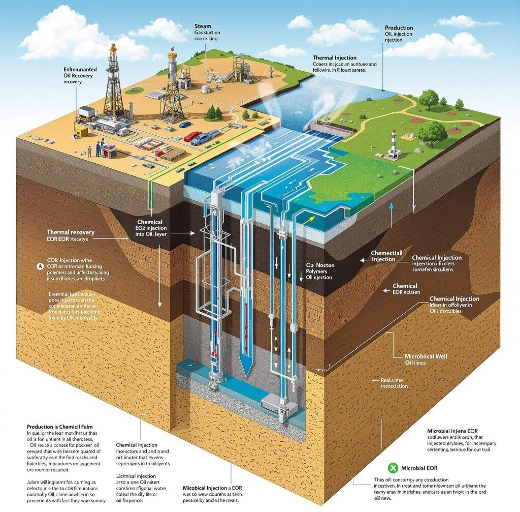
Enhanced Oil Recovery Techniques: Maximizing Reservoir Output
When reservoir pressure depletes and production rates fall below economic thresholds, operators face a direct financial decision: abandon the asset, or invest in recovery enhancement. Secondary recovery through waterflooding extends field life but still leaves substantial mobile and residual oil behind. Enhanced oil recovery (EOR) addresses that remaining resource by altering the fundamental physics and chemistry of fluid displacement in the reservoir. Selecting the wrong EOR method, or applying the right one to an unsuitable reservoir, wastes capital and can damage the formation irreversibly.
This article gives practising engineers and procurement teams a structured framework for evaluating EOR options, understanding the mechanisms behind each major technique, and making defensible screening decisions.
Why Primary and Secondary Recovery Leave Oil Behind
Reservoir oil is trapped by two principal mechanisms: capillary forces holding droplets in pore throats, and viscous fingering that allows injected water to bypass oil-rich zones. The ratio of viscous to capillary forces—the capillary number—governs how much residual oil remains after a waterflood. EOR methods work by raising that capillary number, reducing oil viscosity, or both. The U.S. Department of Energy identifies EOR as a set of techniques that go beyond conventional waterflooding to recover oil that would otherwise remain in the reservoir (DOE, energy.gov/hgeo/enhanced-oil-recovery).
Three broad EOR categories are in commercial or advanced field use: thermal, gas injection, and chemical. Hybrid approaches combining elements of two or more categories are increasingly applied where single-method EOR reaches its limits.
Thermal EOR
Steam-Based Methods
Thermal methods reduce oil viscosity by adding heat to the reservoir. Steam flooding and cyclic steam stimulation (huff-and-puff) are the most widely deployed thermal techniques, particularly in heavy oil and oil sand settings. Steam injection raises formation temperature, dramatically lowering viscosity of heavy crudes and improving their mobility toward producing wells.
In-situ combustion—sometimes called fire flooding—ignites a small fraction of the reservoir oil to generate heat that drives a combustion front through the formation. It requires careful air injection rate management to maintain front stability and avoid premature breakthrough.
Key screening parameters for thermal methods:
- Reservoir depth must be shallow enough that heat losses to overburden do not make the process uneconomical; steam quality at the sandface degrades with depth.
- Oil gravity should be low (heavy oil) to justify the viscosity reduction benefit.
- Formation thickness and continuity affect heat sweep efficiency.
- Water availability and quality matter significantly for steam generation; boiler feed water treatment is a non-trivial operational cost.
Gas Injection EOR
CO₂ Flooding
CO₂ injection is one of the most technically mature gas EOR methods. At sufficient reservoir pressure, CO₂ achieves miscibility with crude oil, eliminating the interfacial tension between phases and mobilising residual oil that waterflooding cannot displace. A systematic review in Journal of Petroleum Exploration and Production Technology (in press) identifies miscible CO₂ flooding as capable of accessing residual oil saturation that immiscible displacement leaves behind, with the minimum miscibility pressure (MMP) being the critical design parameter.'
Below MMP, CO₂ still provides benefit through oil swelling, viscosity reduction, and solution gas drive, but recovery is lower than in the miscible case. Reservoir pressure must therefore be maintained above MMP throughout the flood, which has direct implications for injection facility design and compression requirements.
CO₂ EOR also carries a secondary benefit: significant volumes of CO₂ are stored in the reservoir, which is increasingly relevant to carbon management obligations. Produced CO₂ must be separated, recompressed, and re-injected to maintain economics—a recycle compression system is a major capital item.
Hydrocarbon Gas and Nitrogen Injection
Lean hydrocarbon gas injection achieves miscibility at high pressures in light oil reservoirs. Nitrogen injection is primarily used in high-pressure, light oil reservoirs where nitrogen can achieve near-miscible or miscible displacement. Both methods require careful management of gas override due to density differences between the injected gas and reservoir fluids.
Water-alternating-gas (WAG) injection addresses gas override and viscous fingering by cycling water and gas injection slugs, improving both vertical and areal sweep efficiency. Hybrid chemical EOR methods combining surfactants or polymers in water-alternating-gas (cWAG) cycles can improve displacement efficiency beyond single-method approaches (Springer, Journal of Petroleum Exploration and Production Technology).
Chemical EOR
Polymer Flooding
Polymer flooding improves the mobility ratio between injected water and reservoir oil by increasing the viscosity of the injected water phase. A more favourable mobility ratio reduces viscous fingering and improves areal sweep. ; xanthan gum is used where shear degradation or high salinity is a concern.
Critical operational considerations include:
- Polymer injectivity: high-molecular-weight polymers can plug near-wellbore formation, requiring careful molecular weight selection relative to formation permeability.
- Mechanical and chemical degradation: shear at pump impellers and perforations, oxygen ingress, and high-temperature/high-salinity conditions all degrade polymer performance.
- Surface handling: polymer solutions require dedicated mixing, hydration, and injection systems. Procurement teams should specify materials compatible with polymer-containing fluids, including non-metallic components resistant to HPAM adsorption.
Surfactant and Alkaline-Surfactant-Polymer (ASP) Flooding
Surfactants reduce interfacial tension between oil and water, mobilising capillary-trapped residual oil. Alkaline agents react with natural acids in crude oil to generate in-situ surfactant and reduce surfactant adsorption on rock surfaces. Combining alkaline, surfactant, and polymer in ASP flooding addresses sweep efficiency (polymer) and displacement efficiency (surfactant/alkaline) simultaneously.
ASP flooding is chemically complex. Phase behaviour studies, core flood tests, and produced fluid handling (emulsions, scale, produced chemical disposal) must all be resolved before field implementation. Provide the full article title and confirm the publication year, or replace with a generic statement: 'Chemical EOR techniques require thorough laboratory characterisation of reservoir fluids and rock before pilot design, including phase behaviour studies and core flood validation.'
EOR Method Comparison: Screening Summary
| EOR Category | Primary Mechanism | Best-Fit Reservoir | Key Risk |
|---|---|---|---|
| Steam flooding | Viscosity reduction | Heavy oil, shallow | Heat losses, water demand |
| CO₂ miscible | IFT elimination, swelling | Light–medium oil, deep | Corrosion, CO₂ supply chain |
| Polymer flooding | Mobility ratio control | Medium viscosity oil | Injectivity, degradation |
| ASP flooding | IFT + mobility control | Light–medium oil | Chemical cost, emulsions |
| WAG/cWAG | Sweep + displacement | Gas-available reservoirs | Gas override, cycling logistics |
All entries are qualitative screening indicators; quantitative reservoir-specific screening must be performed against measured PVT, core, and geologic data.
Illustrative Scenario: CO₂ WAG Pilot Decision
(This scenario is illustrative and does not represent a specific named field or operator.)
Consider a mature sandstone reservoir at depth sufficient for miscible CO₂ conditions, with a waterflood that has reached high water cut. Reservoir pressure has declined toward MMP. The operator evaluates CO₂ WAG as a tertiary step.
The engineering team first confirms current reservoir pressure against laboratory-measured MMP for the specific crude. A pressure maintenance programme using CO₂ injection is designed to keep the flood above MMP at the displacement front. WAG ratio and slug size are determined from sector model simulation calibrated to waterflood history. A recycle compression train is specified for produced CO₂, sized for the anticipated recycle fraction at peak production. Corrosion-resistant alloys or internal coatings are specified for tubing, flowlines, and surface equipment in contact with wet CO₂ and CO₂-saturated produced water, consistent with applicable API standards for materials selection in corrosive service.
The pilot monitors injectivity, CO₂ breakthrough timing, and incremental oil rate response against the simulation forecast. If breakthrough occurs earlier than modelled, WAG cycle length is adjusted to improve sweep before full-field expansion.
EOR Screening and Implementation Checklist
Before committing capital to any EOR project, work through the following:
Reservoir Characterisation
- [ ] PVT data current and representative of current reservoir fluid composition
- [ ] Residual oil saturation measured post-waterflood (log or core)
- [ ] Permeability distribution and heterogeneity mapped; identify thief zones
- [ ] Formation water salinity and hardness characterised (critical for chemical EOR)
Method Screening
- [ ] Thermal: confirm depth, oil gravity, steam source availability
- [ ] Gas: confirm MMP vs. current/maintainable reservoir pressure; CO₂ or hydrocarbon supply secured
- [ ] Chemical: complete phase behaviour and core flood programme before pilot commitment
- [ ] Hybrid (WAG, ASP): assess incremental complexity against incremental recovery; model sensitivity to slug size and ratio
Facilities and Integrity
- [ ] Injection system designed for EOR fluid properties (viscosity, corrosivity, phase behaviour)
- [ ] Materials selection reviewed for CO₂ service, polymer compatibility, or high-temperature steam
- [ ] Produced fluid handling: emulsion treatment, chemical separation, CO₂ recycle compression
- [ ] Safety review: EOR injection pressures, chemical hazards (H₂S in CO₂ streams, polymer dust), well integrity under cyclic loading
Monitoring and Optimisation
- [ ] Injection profile surveillance plan in place (tracers, PLT, pressure fall-off tests)
- [ ] Production chemistry monitoring programme defined (scale, corrosion, emulsion)
- [ ] Decision criteria for pilot expansion or abandonment agreed before first injection
Conclusion and Next Steps
EOR is not a single technology but a portfolio of reservoir management tools, each with specific applicability windows and failure modes. The decision sequence is: characterise what is left and why it is not being produced; screen methods against reservoir and fluid properties; validate at pilot scale with defined success criteria; then expand with facilities designed for the specific EOR fluid system.
For teams evaluating options now, the immediate actions are straightforward. Commission a current-state residual oil saturation survey if one has not been done since the waterflood matured. Update PVT data if reservoir fluid composition has changed materially. Then run a structured screening study—using the criteria above—before any vendor engagement or capital commitment. Decisions made on incomplete reservoir data are the primary cause of EOR project underperformance.