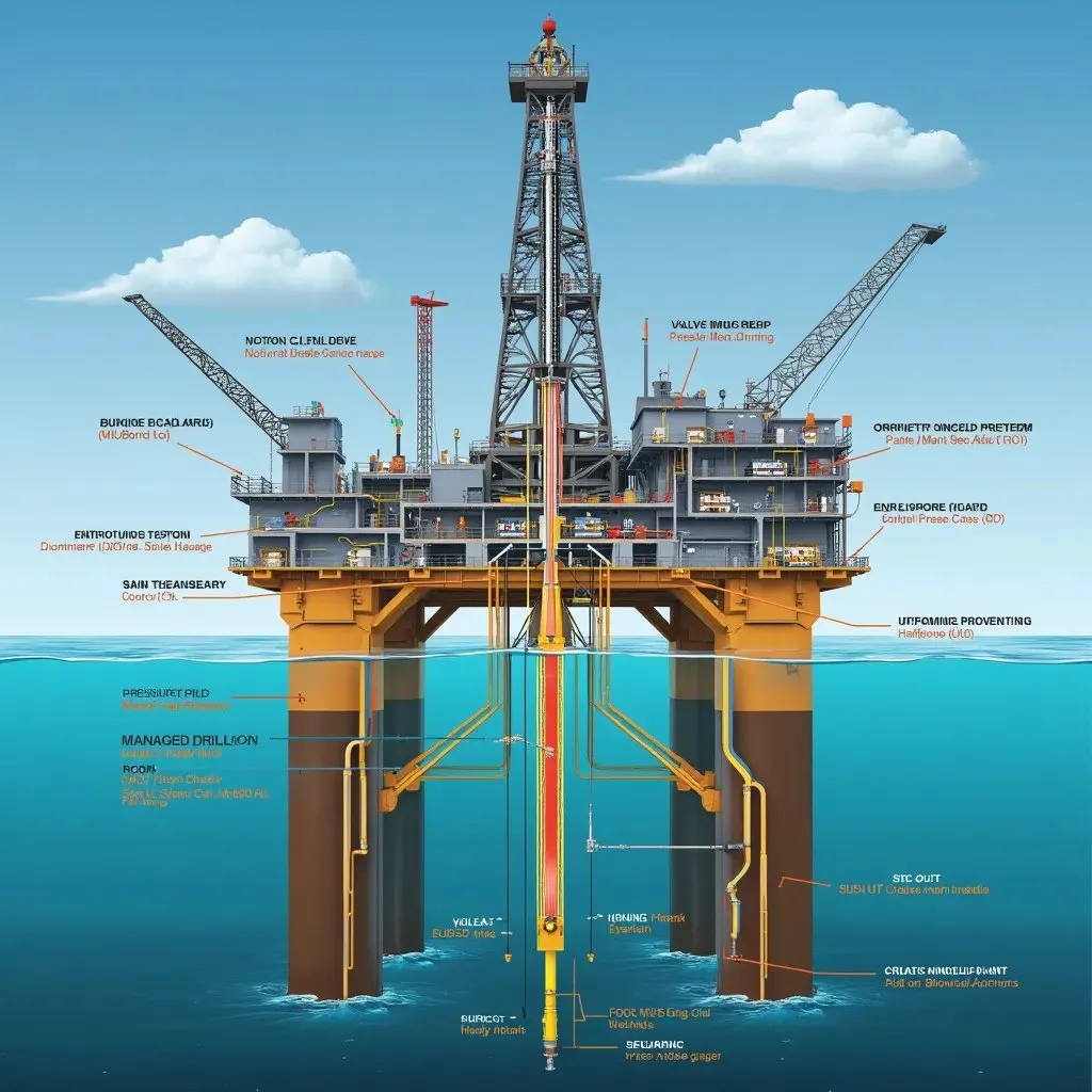
Mitigating Environmental Risks in Offshore Oil Production
A subsea wellhead lets go. Produced water goes overboard above the consent limit. Cuttings stack up on the seabed under the rig. Any one of those brings a regulator to the table, a remediation bill, and a reputational hit that can delay the next licence award. So environmental risk management is not a compliance exercise bolted on at the end of a project. It is a core engineering discipline, and it runs from front-end design all the way through decommissioning.
What follows: the principal environmental hazard categories, the control hierarchy that applies to each, and practical decision guidance for engineers and maintenance leads working on offshore installations.
Understanding the Environmental Hazard Landscape
Offshore oil and gas puts pressure on the environment across the whole asset lifecycle—exploration drilling, production operations, well intervention, and decommissioning. The OSPAR Quality Status Report 2023 records impacts at every one of those stages, from seismic surveys through to infrastructure removal, with effects on water column chemistry, seabed integrity, and atmospheric emissions.
The Pontinha et al. (2025) literature review splits offshore energy environmental risks into four buckets: physical disturbance, chemical contamination, noise, and electromagnetic effects. That framework maps cleanly onto the engineering controls an operations team actually has to hand.
Primary Contamination Pathways
Produced water (PW) discharge is the largest volume effluent stream from any producing offshore installation. PW carries dispersed oil, dissolved organics, naturally occurring radioactive material (NORM), and treatment chemicals.
Drill cuttings and drilling fluids carry hydrocarbons and synthetic or water-based mud constituents to the seabed. The Frontiers in Environmental Science review of deep-water impacts highlights that cuttings piles can persist on the seabed for extended periods, with physical smothering and chemical toxicity affecting benthic communities in the vicinity of the wellhead.
Accidental hydrocarbon releases—well blowouts, pipeline failures, riser leaks, and storage tank overflows—are low-frequency, high-consequence events. The UNEP Finance Initiative 2023 briefing on harmful marine extractives identifies these events as carrying material financial risk to operators and their insurers, beyond the direct environmental liability.
Atmospheric emissions from combustion, flaring, venting, and fugitive leaks contribute to greenhouse gas loading and local air quality degradation. Atmospheric dispersion does take the acute marine toxicity out of the picture, but methane slip and flare efficiency land straight in the operator's carbon reporting obligations.
Regulatory and Standards Context
Environmental management for offshore installations sits inside a layered framework: international conventions, regional agreements, and national competent authority requirements.
OSPAR Decision 2000/3 governs the use and discharge of offshore chemicals in the North-East Atlantic. Every chemical gets screened through the OSPAR HMCS (Harmonised Mandatory Control Scheme) before use. That has direct procurement implications—a chemical approved in one jurisdiction may be restricted in another OSPAR contracting party's waters.
The applicable IMO MARPOL Annex I requirements set discharge standards for oil in bilge water and ballast water from offshore units that are classed as ships under international maritime law. Many fixed and floating offshore installations fall outside MARPOL jurisdiction, though. In the North-East Atlantic, OSPAR Decision 2000/3 is the primary regulatory framework for offshore discharges.
NOPSEMA's Oil Pollution Risk Management guidance (N-04750-GN1488) provides a structured methodology for identifying, assessing, and controlling oil pollution risks that is applicable beyond the Australian jurisdiction as a best-practice reference. It requires operators to demonstrate that risks are reduced to as low as reasonably practicable (ALARP) and that oil spill response capability is matched to the credible worst-case scenario at the specific location.
Process safety management underpins prevention of major hydrocarbon releases. IEC 61511 (Functional Safety: Safety Instrumented Systems for the Process Industry Sector) defines the requirements for safety instrumented functions (SIS) that protect against loss of containment. High-integrity pressure protection systems (HIPPS) on subsea trees and topsides process equipment that are designed as SIS are validated under this standard. Other safety functions, including passive devices and non-SIS active controls, may be designed under alternative standards such as API RP 14C.
Engineering Controls by Hazard Category
Produced Water Management
The control hierarchy for PW runs: minimise reservoir water production through reservoir management → maximise reinjection → treat and discharge within consent limits → monitor and report.
Reinjection eliminates the marine discharge pathway entirely and is the preferred option where injection well capacity and reservoir pressure permit. Where surface discharge is unavoidable, treatment trains typically combine hydrocyclones, flotation units, and polishing technologies. The selection and sizing of each stage must account for variable crude composition and water cut across the production profile—a system optimised for early-life PW chemistry may underperform as water cut increases.
Monitoring is not optional. Continuous or frequent sampling of oil-in-water concentration, with calibrated instrumentation traceable to a recognised method, is the basis for demonstrating consent compliance. Trend the measured values against the consent limit and investigate any sustained upward drift before it becomes a breach.
Drilling Waste Control
Selection of drilling fluid type is the primary control. Water-based muds (WBM) carry lower environmental risk than oil-based muds (OBM) or synthetic-based muds (SBM) when cuttings reach the seabed. Where OBM or SBM is operationally necessary—typically for wellbore stability in reactive shales or HPHT wells—cuttings must be processed to reduce base fluid retention to the lowest achievable level before any permitted discharge, or transported to shore for thermal treatment.
Cuttings injection (CI)—grinding cuttings to a slurry and injecting into an annular disposal well or dedicated formation—eliminates the seabed discharge pathway. CI feasibility depends on formation injectivity and proximity of a suitable disposal interval. Evaluate it at the well design stage, not as an afterthought once the bit is on bottom.
Hydrocarbon Release Prevention and Response
Prevention centres on well integrity, process containment integrity, and functional safety system performance.
Well integrity: Dual-barrier philosophy must be maintained throughout the well lifecycle. Annulus pressure monitoring provides the primary surveillance tool for detecting barrier degradation. Any sustained casing pressure that cannot be attributed to a known benign source requires formal investigation under the operator's well integrity management system.
Process containment: Corrosion management is the dominant degradation mechanism for topsides pipework and subsea flowlines. Inspection intervals and methods (ultrasonic thickness measurement, intelligent pigging, chemical inhibition monitoring) should be risk-ranked using a recognised RBI (risk-based inspection) methodology; API 580 (Risk-Based Inspection) provides the framework for that assessment.
Functional safety: Safety shutdown valves, emergency shutdown systems, and blowdown systems protecting against loss of containment must be maintained to their required safety integrity level (SIL) as determined under IEC 61511. Proof testing intervals must be honoured; deferrals require formal management of change and documented risk acceptance.
Spill response: Oil spill response planning must be location-specific. Factors including water depth, distance from shore, prevailing currents, ecologically sensitive receptors, and seasonal weather windows all affect the credibility and effectiveness of mechanical recovery, dispersant application, and in-situ burning. NOPSEMA's guidance explicitly requires response capability to be matched to the credible worst-case scenario—a generic plan copied from another asset in a different sea area does not meet this intent.
Atmospheric Emissions and Flaring
Continuous flaring of associated gas where export or reinjection is technically feasible is increasingly scrutinised by regulators and investors. The engineering priority is to maximise gas utilisation: fuel gas for power generation, gas lift, or export compression. Where flaring is unavoidable—during well testing, start-up, or emergency depressurisation—combustion efficiency should be maintained through proper flare tip selection, purge gas management, and pilot flame reliability.
Fugitive emission surveys using optical gas imaging (OGI) cameras or equivalent technology identify leaks at flanges, valve stems, and instrument connections that would otherwise go undetected by fixed point detectors. Establish a baseline survey on commissioning and repeat at defined intervals, prioritising high-flow potential leak sources.
Illustrative Scenario: Produced Water Discharge Exceedance
This scenario is illustrative and does not represent a specific named incident.
An FPSO operating in a mature field experiences a step increase in water cut following a well intervention. The produced water treatment system, designed for the original water cut envelope, begins producing effluent at oil-in-water concentrations that approach the consent limit. The operations team, focused on production optimisation, does not flag the trend until a routine sample triggers a reportable exceedance.
A structured response would have included: trending PW treatment performance against the original design envelope as water cut increased; triggering a formal review of treatment capacity when measured values showed sustained upward movement toward the limit; and engaging the chemical treatment supplier to evaluate whether dosing adjustments or additional polishing capacity could restore margin before a breach occurred.
The lesson: track environmental performance indicators with the same rigour as production KPIs. Not retrospectively, once a consent limit has already been crossed.
Environmental Risk Management Checklist
Use this checklist at pre-operations review, annual audit, and following any significant change to production profile or well stock.
Produced Water
- [ ] PW treatment system capacity validated against current and projected water cut
- [ ] Oil-in-water monitoring instrumentation calibrated and sampling frequency documented
- [ ] Reinjection volumes and disposal well injectivity reviewed against production forecast
- [ ] OSPAR/MARPOL chemical approvals current for all PW treatment chemicals
Drilling Waste
- [ ] Drilling fluid type selection documented with environmental justification
- [ ] Cuttings discharge or cuttings injection route confirmed at well design stage
- [ ] Base fluid retention on cuttings measured and recorded against permitted limit
Hydrocarbon Release Prevention
- [ ] Well annulus pressure monitoring active and alarm response procedure current
- [ ] RBI programme up to date; no overdue inspection items without documented deferral
- [ ] SIL-rated safety functions proof tested within required interval per
IEC 61511 - [ ] Oil spill response plan reviewed against current asset configuration and receptor mapping
Atmospheric Emissions
- [ ] Flaring volumes tracked and root causes of non-emergency flaring documented
- [ ] Fugitive emission survey completed within defined interval; findings closed out
- [ ] Flare combustion efficiency maintained through pilot monitoring and tip inspection
Conclusion and Next Steps
Environmental risk in offshore oil production does not get managed by a single technology or a single team. It needs integrated engineering controls across the production system, held at their design intent for the life of the asset.
For any operations or maintenance lead, three things come first. Confirm that produced water treatment performance is being trended against current water cut, not original design assumptions. Verify that all SIL-rated safety functions protecting against loss of containment are within their proof test interval. And make sure the oil spill response plan reflects the current asset configuration and has been exercised recently.
For procurement teams, the entry point is chemical screening under OSPAR HMCS before any new treatment chemical is introduced to an OSPAR-regulated installation. Approval is not transferable between jurisdictions, and a non-compliant discharge traced to an unapproved chemical carries both regulatory and contractual liability.
Environmental performance and production integrity share the same engineering foundations. Corrosion management, well integrity surveillance, and functional safety maintenance protect the asset and the marine environment at the same time. Run them as one programme.