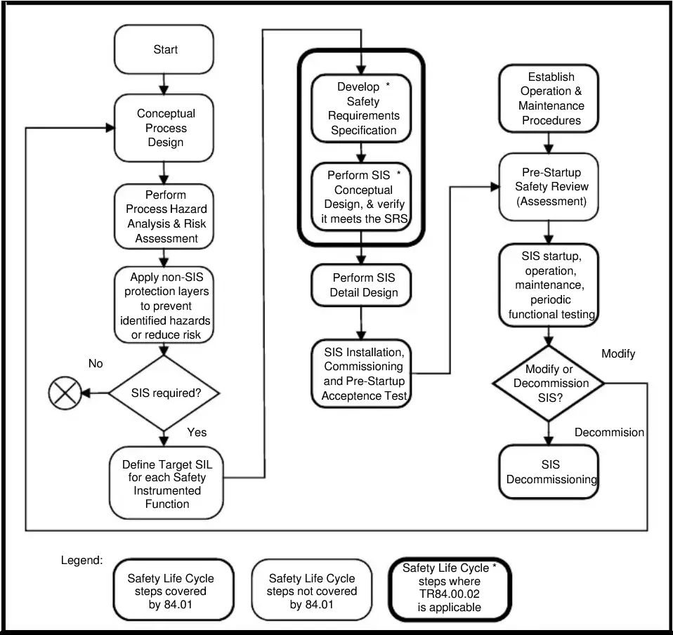
SIL Verification Demystified: Applying ISA-TR84.00.02 for Safety Instrumented Functions in Oil & Gas
A Safety Instrumented Function that carries a SIL 2 target on paper but fails the verification calculation is not a SIL 2 function—it is a liability dressed in documentation. Yet across operating facilities, SIL verification is routinely treated as a paperwork exercise: numbers are entered into a software tool, a green result appears, and the file is closed. When an incident investigation later opens that file, the gaps become expensive. This article walks through the verification methodology described in ISA-TR84.00.02, explains where practitioners consistently go wrong, and provides decision guidance for engineers, maintenance leads, and procurement teams who need defensible results.
What SIL Verification Actually Is—and Is Not
SIL selection answers the question: what risk reduction does this Safety Instrumented Function (SIF) need to deliver? SIL verification answers a different question: does the as-designed SIF actually deliver that risk reduction, given the specific hardware, architecture, proof-test interval, and diagnostic coverage selected?
ISA-TR84.00.02 is the technical report that supports IEC 61511, the functional safety standard for process sector Safety Instrumented Systems (SIS). The technical report provides worked calculation methods—Simplified Equations, Markov analysis, Fault Tree Analysis, and reliability block diagrams—that allow engineers to calculate the Probability of Failure on Demand (PFD) or the Probability of Failure per Hour (PFH) for a SIF and compare the result against the SIL target established during the hazard and risk assessment.
The distinction matters for procurement teams: buying a transmitter with a SIL 2 certificate does not make the SIF SIL 2. The certificate addresses the device in isolation. Verification addresses the entire SIF loop—sensor subsystem, logic solver, and final element subsystem—operating under site-specific conditions.
The Calculation Framework
PFD vs. PFH: Choosing the Right Metric
ISA-TR84.00.02 directs engineers to use PFD (average probability of failure on demand) for demand-mode SIFs and PFH (probability of dangerous failure per hour) for high-demand or continuous-mode SIFs. Selecting the wrong metric for the operating mode is a fundamental error that invalidates the verification result regardless of how carefully the arithmetic is done.
A high-integrity pressure protection system on a wellhead typically operates in low-demand mode: the SIF is demanded infrequently, and PFD is the correct metric. A burner management system flame safeguard operating continuously is assessed using PFH. Confirm the operating mode before opening any calculation tool.
Subsystem Decomposition
ISA-TR84.00.02 structures the SIF as three subsystems:
- Sensor subsystem (initiating elements, including transmitters, switches, and voting arrangements)
- Logic solver subsystem (safety PLC, relay logic, or pneumatic logic)
- Final element subsystem (valves, actuators, position switches, solenoids)
Each subsystem contributes to the overall SIF PFD. The total SIF PFD is the sum of the three subsystem PFD values. This additive property means that a weak final element subsystem can consume the entire SIL budget even when the sensor and logic solver are well-specified.
Key Input Parameters
The calculation requires, for each component:
| Parameter | What it represents | Where to obtain it |
|---|---|---|
| λ_D (dangerous failure rate) | Rate of failures that could prevent the SIF from operating on demand | Manufacturer SIL data sheet or IEC 61508 certification data |
| DC (diagnostic coverage) | Fraction of dangerous failures detected by automatic diagnostics | Manufacturer data; ISA-TR84.00.02 guidance tables |
| β (common cause failure fraction) | Proportion of failures affecting redundant channels simultaneously | ISA-TR84.00.02 beta factor methodology |
| T_I (proof-test interval) | Time between manual functional tests | Site maintenance schedule |
| T_CE (mean time to restore) | Average repair time following detected failure | Site CMMS historical data |
| Architecture (1oo1, 1oo2, 2oo3, etc.) | Voting logic | SIS design basis |
Every one of these inputs requires engineering judgment and site-specific data. Default or generic values borrowed from reference databases without verification against actual equipment and actual maintenance intervals are a common source of non-conservative results.
Where Verification Calculations Fail in Practice
Proof-Test Interval Optimism
The proof-test interval entered into the calculation must reflect the interval actually achieved in the field, not the interval written in the maintenance procedure. If a procedure specifies annual testing but operational constraints routinely extend the interval, the PFD result is non-conservative. ISA-TR84.00.02 requires that the assumed interval be achievable under normal operating conditions. Maintenance leads should audit actual test completion records before confirming the interval used in verification.
Incomplete Proof-Test Coverage
A proof test that does not exercise the full SIF from sensor to final element does not achieve full credit. Partial stroke testing of a valve, for example, detects a proportion of valve failures but leaves the remainder undetected until a full-stroke test. ISA-TR84.00.02 provides guidance on how to account for partial proof-test coverage in the PFD calculation. Using a full-test credit when only a partial test is performed inflates the apparent risk reduction.
Common Cause Failures Underestimated
The beta factor accounts for failures that defeat redundancy—a single event that causes two independent channels to fail simultaneously. Common cause failures in oil and gas SIFs arise from shared instrument air supplies, common impulse line routing through a heat-affected zone, identical software versions with a common bug, or a single technician incorrectly calibrating multiple transmitters during the same maintenance window. ISA-TR84.00.02 provides a structured beta factor estimation method. Applying a minimum default beta without working through the checklist underestimates common cause risk in architectures where physical or procedural independence has not been rigorously implemented.
Systematic Failures Ignored
PFD calculations address random hardware failures. ISA-TR84.00.02, consistent with IEC 61511, recognises that systematic failures—errors in specification, design, installation, or maintenance—are not captured by reliability arithmetic. A SIF that passes the PFD calculation but has an incorrect trip setpoint in the logic solver, or a valve that fails to close because of incorrect actuator sizing, will not perform. Verification must be accompanied by a functional safety assessment that reviews the SIF specification, cause-and-effect diagram, and commissioning records.
Illustrative Scenario: High-Pressure Separator Overpressure SIF
(This scenario is illustrative and does not represent a specific named facility or incident.)
Consider a high-pressure separator with a SIF designed to close the inlet block valve on high-high pressure. The SIL 2 target requires a PFD in the range defined by IEC 61511 for SIL 2. The architecture uses a single pressure transmitter (1oo1 sensor), a safety PLC logic solver, and a single pneumatically actuated ball valve with solenoid (1oo1 final element).
A preliminary PFD calculation using the manufacturer's dangerous failure rate data and the planned annual proof-test interval produces a result that appears to meet SIL 1 but falls short of SIL 2. The engineer has three options: increase redundancy in the sensor subsystem (e.g., move to 1oo2 or 2oo3 voting), increase proof-test frequency, or improve diagnostic coverage. Adding a second transmitter in 1oo2 voting reduces the sensor subsystem PFD substantially, and re-running the calculation with updated beta factor inputs brings the total SIF PFD within the SIL 2 band—provided the proof-test interval is maintained as planned and the beta factor assumptions about physical separation of the two transmitters are honoured during installation.
This scenario illustrates why verification must be completed before procurement finalises the bill of materials, not after. Discovering an architecture gap after the valve and actuator are on order is a schedule and cost problem. Discovering it after installation is a safety problem.
Practical Checklist for SIL Verification
Use this checklist before submitting a SIF verification for functional safety assessment review.
Scope and Inputs
- [ ] Confirm operating mode (low demand vs. high demand/continuous) and select PFD or PFH accordingly
- [ ] Obtain λ_D and DC values from manufacturer SIL data sheets, not from generic databases, unless site-specific data is unavailable and the generic source is documented
- [ ] Confirm the proof-test interval against the actual maintenance schedule and recent completion records
- [ ] Document partial proof-test coverage separately from full-test coverage and apply the correct credit in the calculation
- [ ] Work through the
ISA-TR84.00.02beta factor checklist for each redundant architecture; do not apply a default value without justification
Architecture and Design
- [ ] Verify that the SIF boundary matches the cause-and-effect diagram: sensor tap-off point to final element seat
- [ ] Confirm that the logic solver is assessed using its own certified failure rate data, not a generic PLC figure
- [ ] Check that solenoid valves, position switches, and limit switches in the final element subsystem are included in the final element PFD—these are frequently omitted
- [ ] Review physical separation and common services for redundant channels; document any shared utilities as common cause contributors
Documentation and Governance
- [ ] Confirm the SIL target is traceable to a documented hazard and risk assessment (Layer of Protection Analysis or equivalent)
- [ ] Record all assumptions, data sources, and deviations in the verification report
- [ ] Schedule a functional safety assessment review of the completed verification before SIS design is frozen
- [ ] Plan a re-verification trigger for any modification that changes architecture, proof-test interval, or component failure rate data
Conclusion and Next Steps
SIL verification is a quantitative engineering activity with specific inputs, methods, and acceptance criteria defined in ISA-TR84.00.02. It is not a software tool output to be accepted without scrutiny of the assumptions behind it. The most common failures—optimistic proof-test intervals, incomplete test coverage credit, underestimated common cause factors, and missing final element components—are all preventable with disciplined input review before the calculation is run.
For engineers beginning or refreshing a SIL verification programme, the practical next steps are:
- Obtain the current edition of
ISA-TR84.00.02and align your calculation templates to its methods and beta factor guidance. - Audit existing SIF verification records against actual proof-test completion data and confirm that assumed intervals are being met.
- Establish a formal management-of-change trigger so that any modification to a SIF—hardware, software, or maintenance procedure—initiates a re-verification review before the change is implemented.
- Engage your functional safety assessor early in the design phase, not at the documentation stage.
A verified SIF is not a guarantee of zero incidents. It is a defensible, quantified demonstration that the design delivers the risk reduction the facility requires. That distinction is worth the rigour.